| Home | Price List | Order Info | P955H PIC Training Course | BMP280 Mini Training Course | PIR & RF Data Training Course |
|
PIC Training Course Mini Course Part 2: LCD, Keypad and ADC and measuring temperature 3 ways Updated January 2026 |
|
This PIC training course is Part 2 of our mini course. It follows that for Part 2 you are expected to have some knowledge of programming. If you have experience of programming but never used a PIC you should find no problem starting here. All the programme code is written in assembler which is the natural language of PIC microcontrollers. We avoid the complex procedures making this the easiest way to learn about programming PICs. This course follows the same well proved pattern of our P955 PIC training cource which has achieved wide spread approval from the readers. Instead of wading laboriously into detailed theory the interest of the reader is captured by jumping straight into creating useful code. We start with some simple programmes to use the push buttons to turn the LEDs on and off. Then we load the LCD and keypad routines from the included software library and adjust the assembler to suit our hardware. It is always best when studying software to have an interesting objective. For this couse the objective is to measure temperature using three different temperature sensors. To do this we need to use the PICs Analogue to Digital Converter so we study the ADC jn chapter 4. In the next three chapters we create code to measure temperature using an LM35 tempersature sensor, a thermistor, then a BMP280 air pressure and temperature sensor. We do not programme the BMP280 to measure air pressure because it requires rather complex code. (That is covered in my Hight and Total Gain Measurement course). |
|
|
|
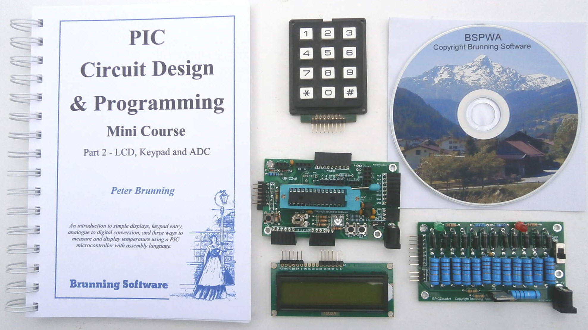
All the experimental code is written to run in a GPICZv8 general purpose PIC training circuit which is shown at the center of this picture. The circuit on the right is a 100 watt load plug in daughter board used when measureing the power of a solar panel. So far there are two daughter boards. The other can be used as a simple grow light controller. The GPICZv8 module has provision to plug in a Brunning Software programmer (P205, P931, P942 or P955) or a PICkit 3 or 4. All the instructions in the Part 2 manual assume that a Brunning Software programmer is being used. |

|
|
If you have Part 1 of the mini course you have a P205 programmer so go for Option 2. |
|
Price List: Option 1. Mini course part 2 complete..... £69.75 including delivery to UK Includes P205 programmer. Supplied built and tested. Book: Mini Course Part 2 156 pages 210x150mm. + GPICZv8 general purpose PIC circuit. + P205 PIC programmer. + USB to PC lead. + 2 line 16 character LCD. + Keypad + PIC18F24K22 + LM35D temperature sensor. + Thermistor temperature sensor. + BMP280 temperature & pressure sensor. + PIC assembler and assembler text on CD + 4xAA battery box + lead |
|
Option 2. Mini course part 2 without P205..... £51.75 including delivery to UK P205 programmer not included. Supplied built and tested. Book: Mini Course Part 2 156 pages 210x150mm. + GPICZv8 general purpose PIC circuit. + 2 line 16 character LCD. + Keypad + PIC18F24K22 + LM35D temperature sensor. + Thermistor temperature sensor. + BMP280 temperature & pressure sensor. + PIC assembler and assembler text on CD + 4xAA battery box + lead |
| Home | Price List | Order Info | P955H PIC Training Course | BMP280 Mini Training Course | PIR & RF Data Training Course |