Home Price List Order Info P955H Course PIR & RF Data Mini Course

PIC Training - PIR and RF Data
2nd Edition


For beginners with some PIC experience
For Windows 7, 8, 10 and 11

Read chapter 1 carefully as this introduces the ideas, then quickly look through chapter 2 which has essential reference information for 16F and 18F PICs. You will refer back to chapter 2 later as you need the information.

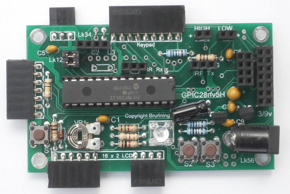
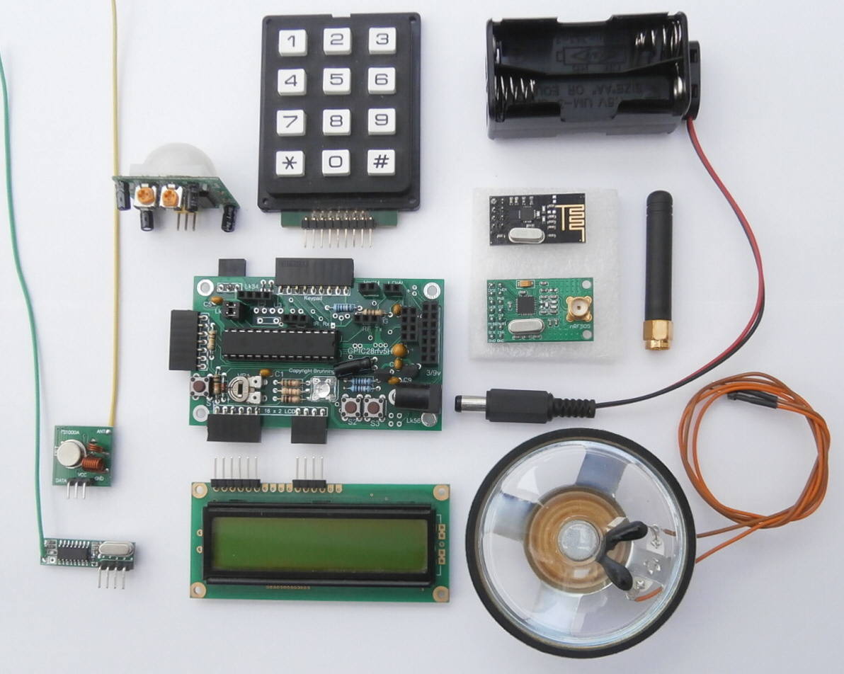
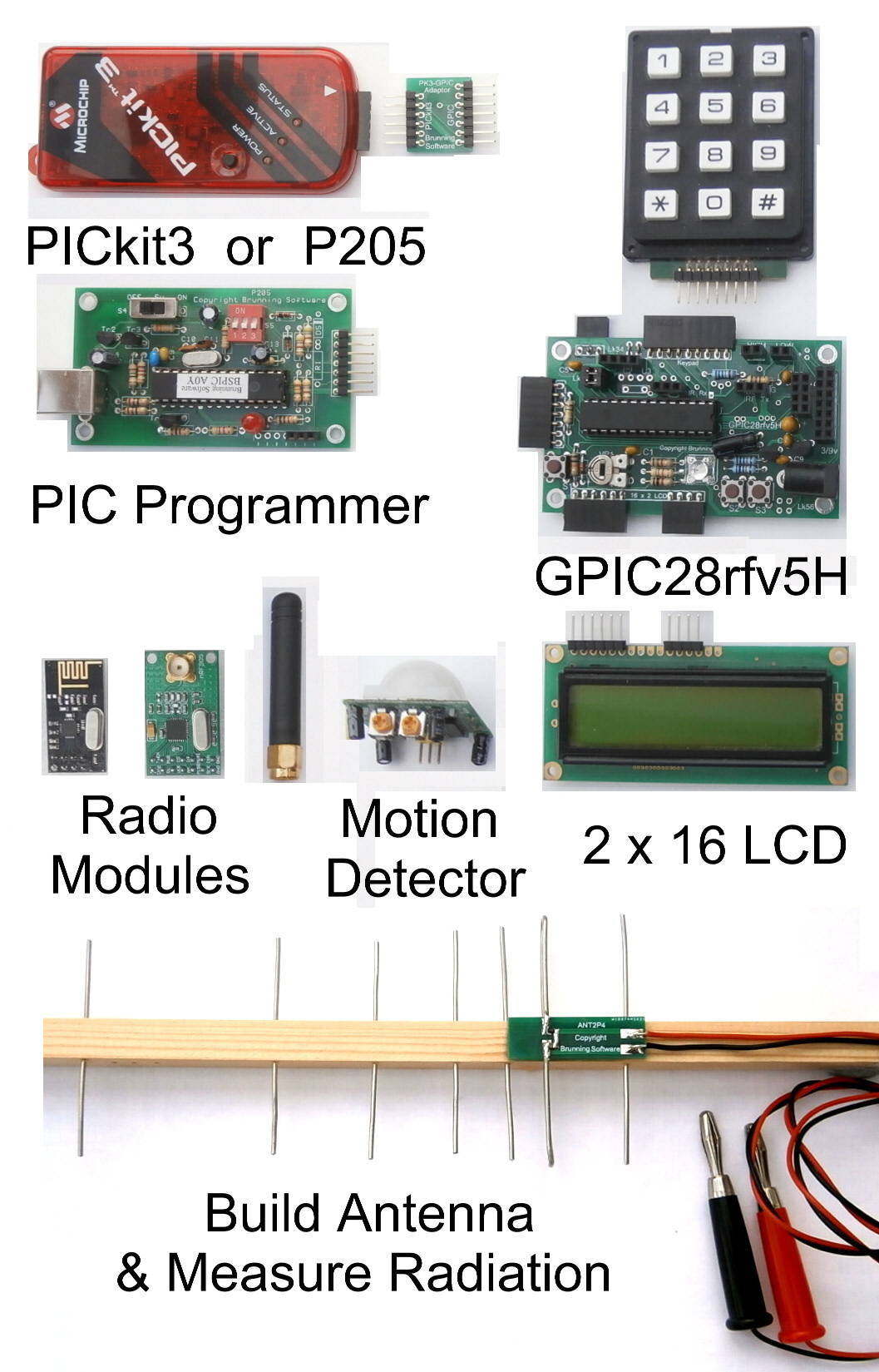
Then as always with our training courses we jump straight in. In chapter 3 we experiment with a few simple programmes. To do this we use a GPIC28rfv5H module which is a general purpose circuit fitted with a 28 pin PIC, a programming socket and a selection of ten sockets for various input and output modules. We run the RGB LED, write text to the LCD, and use the keypad to enter numbers.

In chapter 4 we create a simple system using the GPIC28rfv5H module with a pyrometric motion detector to trigger a warning sound when a person moves within the range of the detector. We use the sleep mode while waiting to maximise the battery life. Then in chapter 5 we learn about the timers and interrupts of the PIC18F25K22.

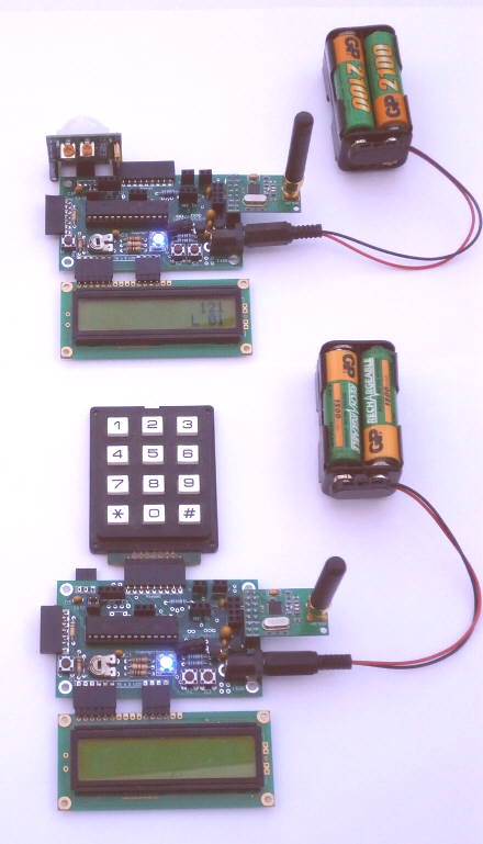
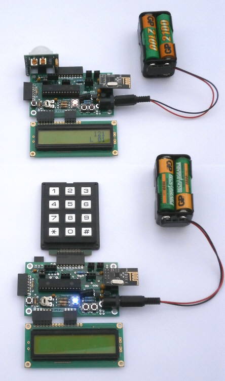
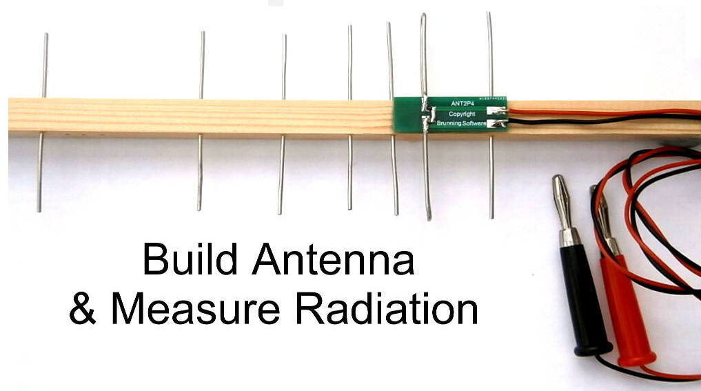
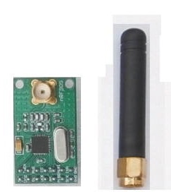
Chapter 6 is an introduction to radio frequency data. We begin with a fundamental explanation of what RF is then experiment with a simple radio data link. The idea is to use a very basic transmitter and receiver so that we can understand the fundamental requirements of radio data transmission and reception. By this means we are able to understand the requirements of the makeup of the data stream. A header to synchronise the receiver, a security address to individualise our data and a few bytes to carry the actual data.

In chapter 7 we expand the simple radio system to create a remote temperature measuring system, and in chapter 8 we complete the simple radio experiments by adding a motion detector to the radio transmitter circuit.

The GPIC28rfv5H is extremely versatile. It has sockets so the following modules can be plugged in.

P205, P955 or PICkit3 programmer.
Battery pack or supply (3 to 9 volts)
2 line x 16 character LCD.
Keypad
Simple 433Mhz radio receiver.
Simple 433Mhz radio transmitter.
nRF905 433/868/915Mhz transceiver.
nRF24L01+ 2.4Ghz transceiver.
HC-SR501 PIR movement detector.
Low power audio output (12mA 3V)
High power audio output (1A 9V)
Infrared transmitter.
Infrared receiver.


All the attachments shown in this picture are used with the GPIC28rfv5H in this course.

Clockwise from 10 to 10.
HC-SR501 motion detector
Keypad
Battery pack
nRF24L01+ 2.4Ghz transceiver
nRF905 433/868/915Mhz transceiver
DC power lead
Loud speaker
2 line 16 character LCD
Simple 433Mhz receiver
Simple 433Mhz transmitter

There is also provision to fit an infrared receiver and transmitter which are not part of this course.

The GPIC28rfv5H can be powered from the programmer or from a 4 cell battery pack or power supply plugged into the DC input socket. The DC input has a 5v regulator and a 3.3v regulator provides power for most of the circuit. Both these regulators have almost zero volt drop below regulation and very low quiescent current.

Chapter 9 introduces the nRF905 433/868/915 Mhz transceiver. This is a complete sophisticated transmitter and receiver constructed on a tiny chip of silicone. It is usually sold mounted on a small PCB with a crystal for the clock and a socket to screw on the antenna. The PCB circuit is designed either for the 433Mhz band or the 868/915Mhz band. We usually supply the 433Mhz version.

The nRF905 is designed to be controlled by a microcontroller so chapter 9 begins with a summary of the essential programming information. Setting the PIC for SPI and sending set up data to the nRF905 can seem rather complex but once the outline procedure has been explained we load the nRF905 library which is an integral part of the Brunning Software PIC assembler BSPWA.

Our experiments begin by programming the same software into two GPIC28rfv5H modules. At switch on both modules set their nRF905 into its receive mode. So both transceivers start by listening on the same channel. To test the system we press the S2 push button on one of the GPIC28rfv5H modules. It immediately transmits ABCD. This is received by the second GPIC28rfv5H module which prints the received data to its LCD. Press S2 on the second GPIC28rfv5H and the data goes the other way.

Once we have proven the system works we edit the software in the fixed GPIC28rfv5H so that it automatically replies every time it receives data.

Then we pick up the mobile system and walk out pressing S2 occasionally to test the system both ways. It is an easy way to get a feeling for the range.

In the experiments for chapter 10 we plug a PIR motion detector into one of the GPIC28rfv5H then edit the software so the mobile system transmits a warning every time the PIR is triggered.

The great advantage of using the nRF905 instead of the simple 433Mhz Tx and Rx is that now we have a transmitter and a receiver in both systems. Once we get the basic system working we edit the software so the PIR transmitter waits for a confirmation transmission from the PIR receiver. If the confirmation is not received the PIR transmitter sends the warning again. We set it up to send up to 5 repeats.

Chapter 11 introduces the nRF24L01+ 2.4Ghz transceiver which is very similar to the nRF905. The nRF24L01+ is usually sold mounted on a small PCB with a crystal for the clock and with the antenna printed on the circuit.

The nRF24L01+ is designed to be controlled by a microcontroller so the chapter begins with a summary of the essential programming information. The outline procedure for programming the nRF24L01+ is almost the same as when using the nRF905. Once the procedure has been explained we load the nRF24L01+ library which is an integral part of the Brunning Software PIC assembler BSPWA.

Our experiments begin by programming the same software into two GPIC28rfv5H modules. At switch on both modules set their nRF24L01+ into its receive mode. So both transceivers start by listening on the same channel. To test the system we press the S2 push button on one of the GPIC28rfv5H modules. It immediately transmits ABCD. This is received by the second GPIC28rfv5H module which prints the received data to its LCD. Press S2 on the second GPIC28rfv5H and the data goes the other way.

Once we have proven the system works we edit the software in the fixed GPIC28rfv5H so that it automatically replies. Then we pick up the mobile system and walk out pressing S2 occasionally to test the system both ways.

In the experiments for chapter 12 we plug a PIR motion detector into one of the GPIC28rfv5H then edit the software so the mobile system transmits a warning every time the PIR is triggered.

Once we get the basic system working we edit the software so the PIR transmitter waits for a confirmation transmission from the PIR receiver. If the confirmation is not received the PIR transmitter sends the warning again. We set it up to send up to 5 repeats.

In chapter 13 we lean how to build a simple 2.4Ghz antenna with a microwave diode and low inductance capacitor which will generate a DC output high enough to be displayed on a normal multimeter. The microwave diode and capacitor are so tiny it is almost impossible to solder them normally. So we have created a small PCB which we supply with these two components already fitted. We also supply enough 1.2mm tinned copper wire, DC output leads and two plugs. That leaves you with the task of buying a 250mm length of 10mm x 12mm wooden rod, drilling seven 1.4mm holes as directed in the book, and assembling the antenna.


When we have built the antenna we need a reference signal to test its operation. We solve this by modifying the software created in chapter 12 so we can set the nRF24L01+ into its continuous carrier mode. We also arrange so that pressing the S3 button on the GPIC28rfv5H adds a step value into the channel number. This arrangement makes it easy to move the test signal across the whole 2.4Ghz band.

In chapter 14 we edit the software created in chapter 12 so that we can use the keypad to enter the channel number and the size of the step. This makes it easy to move the PIR system to a different channel if a problem with interference crops up.


In chapter 15 we edit the software created in chapter 10 so we can use the keypad to set the channel number, step size and frequency band, when using the nRF905. Do remember there are two versions of the nRF905 PCB module. The usual one we supply covers the 433Mhz band. The other version covers both 868 and 915Mhz bands. The new keypad routine is perfect for experimenting with all three bands. You will need to swap between the two versions of nRF905 but the same software is used in the PIC.
Hardware & software Supplied
All options include the following....

Book: Experimenting with PIR and RF Data, 2nd edition
or
Book: Experimenting with PIR and RF Data, PICkit3+MPLAB X edition

2 off GPIC28rfv5H module
2 off 2 line x 16 character LCD
1 off keypad
2 off 4 cell battery holder
2 off plug in battery lead

1 off HC-SR501 motion detector
1 off waterproof mylar loud speaker

1 off simple 433Mhz transmitter
1 off simple 433Mhz receiver

2 off nRF905 433Mhz transceiver module
or
2 off nRF905 868/915Mhz transceiver module

2 off nRF24L01+ 2.4Ghz transceiver module

1 off ANT2P4 PCB with diode and capacitor fitted
1 off length of 1.2mm tinned copper wire
1 off black DC lead
1 off red DC lead
1 off black banana plug
1 off red banana plug

1 off BSPWA PIC assembler on CD with RF library


Option 1. PIR and RF Data Course..... £145
including delivery to UK

Standard PIR and RF Data PIC Training Course

All the "Hardware & software" listed above with
Book: Experimenting with PIR and RF Data, 2nd edition
and 2 off nRF905 433Mhz transceiver module
+ 1 off P205 PIC programmer
+ 1 off USB to PC lead


Option 2. PIR and RF Data Course without P205..... £129
including delivery to UK

You must already have a P205, P931, P942 or P955 programmer.

All the "Hardware & software" listed above with
Book: Experimenting with PIR and RF Data, 2nd edition
and 2 off nRF905 433Mhz transceiver module


Option 3. PIR & RF Data Course, PICkit3+MPASM X edition..... £131
including delivery to UK

You must own or buy a PICkit3 or 4. We do not supply PICkit3 or 4

All the "Hardware & software" listed above with
Book: Experimenting with PIR & RF Data, PICkit3+MPASM X edition
and 2 off nRF905 433Mhz transceiver module
+ 1 off adaptor


If you require an option not listed
or delivery to a country other than the UK
please send an email request to.....
pic (at) brunningsoftware (dot) com

In the UK the 433Mhz and 868Mhz bands can be used.
The 915Mhz band is used in the USA.

Home Price List Order Info P955H Course PIR & RF Data Mini Course