Home Price List Order Info P955H PIC Training Course PIR & RF Data Training Course PIC Mini Training Course

P955H Book 5: Experimenting with
20 Pin PICs and MOSFETs £31.60

The most popular size of PIC has always been the 18 pin version but that is a loner as it is not pin compatible with any other size of PIC. The 8 pin, 14 pin and 20 pin PICs arrived some time later and have been made pin for pin compatible with each other. For example a 20 pin PIC will run correctly in circuits designed for a 14 pin or an 8 pin PIC. The point is not that we ever want to do that but often we do need to add more pins to an existing design. For this reason over the years 8 pin, 14 pin and 20 pin PICs have become more and more popular.

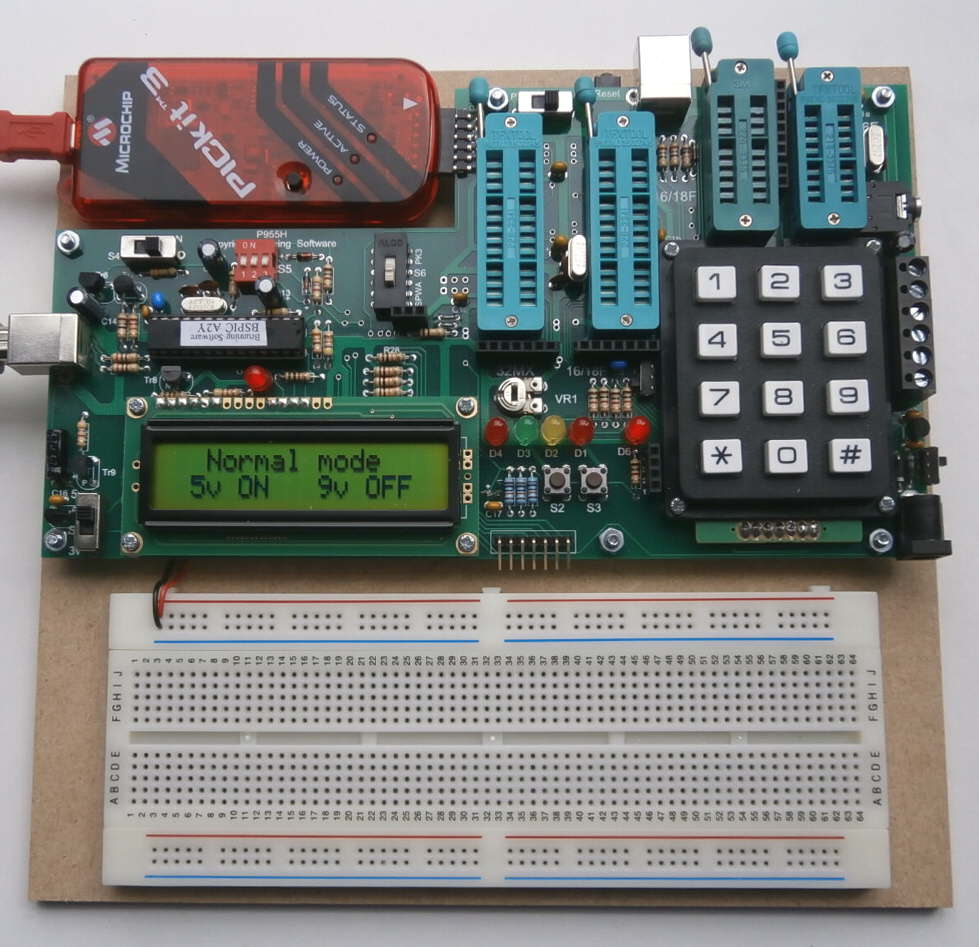
In January 2016 we added one more ZIF socket to our P955 training circuit and renamed it P955H. We have wired the 20 pin ZIF socket so 14 pin and 20 pin PICs can use the LEDs, push buttons, LCD and keypad as do 18 pin and 28 pin PICs. After wiring that part of the circuit the 20 pin ZIF socket still had four unused input/outputs so we added four 14A MOSFETs to the PCB and wired them to the unused pins.

The MOSFETs have a relatively large chip in a tiny package and are rated for 14A continuous current if the case is kept below 25 degree C. In the P955H they are soldered to a large area of copper track which acts as a small heat sync. In the P955H circuit we rate them for 5A maximum continuous total current for all four MOSFETs. i.e. If only one is turned on it can carry 5A continuous but if all four are turned on each one can carry 1.25A continuous current.

The gates of the MOSFETs connect directly to the 20 pin PIC when it is fitted in the 20 pin ZIF socket. The drains (outputs) of the MOSFETs are wired to a block of screw terminals which can be seen in the picture to the right of the keypad. There are six screw terminals. One for +V which connects to the DC input socket at the bottom right of the PCB, four connect to the drains, and the last one connects to ground.
The 5th Book Experimenting with 20 Pin PICs and MOSFETs starts by introducing 14 pin PICs. We flash the LEDs write text to the LCD and use the keypad to write numbers to the LCD. Then we move the 14 pin PIC to the plugboard and fit a 20 pin PIC in the 20 pin ZIF socket. We connect the 5v supply, ground and the serial input and output lines to the 14 pin PIC then experiment sending serial text data from the 14 pin to the 20 pin PIC which displays it on the LCD.

Then it is time to experiment with the MOSFETs. We start by connecting LEDs to the screw terminals then programme the 20 pin PIC with a simple test programme to light the LEDs one a time. That proves the MOSFETs and screw terminals are correctly wired. Then we wire a DC motor to the screw terminals and experiment with controlling the speed of the motor by monitoring the emf which it generates. If the emf drops we increase the mark space ratio if the emf rises we decrease the mark space ratio. By this means we are able to keep the speed constant while maintaining the maximum full voltage torque for when the load increases. Simple pulse width adjustment for speed control dramatically reduced the available torque particularly when using small DC motors.

The next task is to learn about stepper motors. We start with a simple explanation of how they work then we load the library text. The libraries are an integrated part of BSPWA. All that is needed is a few clicks to select the library which you require.

Wiring the circuit is just as easy. All that is needed is to fit a 20 pin PIC into the 20 pin ZIF socket and follow the instructions to wire a six lead stepper motor to the screw terminals. That creates a sophisticated circuit with LCD and keypad so we can easily experiment with various speed and acceleration parameters.

Then we take this a stage further and programme the PIC so it can receive the speed, acceleration and number of steps from your PC. To do this we also create a simple programme using Visual C# (as learnt from P955H book 3) which allows us to use the PC mouse to create and send the stepper motor control data - number of steps, maximum speed and acceleration characteristic.

In the last chapter we study micro stepping from first principles then experiment with the ideas.

This book is wirobound to open flat, 240mm x 170mm, 130 pages.

Price list:-

You must already own a P955H or place this order at the same time as buying the P955H.

Order code P955H Book 5:-

  1. Book 5: Experimenting with 20 Pin PICs & MOSFETs....... £12.50
  2. PIC16F1823 (14 pin) PIC16F1828 (20 pin) Test PICs.......... £ 4.10
  3. Resistors, LEDs and leads (no motors)............................. £ 2.50
  4. CD of latest BSPWA assembler including stepper library.... £ 7.00
  5. Royal Mail postage to UK................................................ £ 5.50
Book 5 extension total price inc UK postage...... £31.60
To pay using PayPal click.....
Resistors, LEDs and Links
for Book 5 Experiments


2 off red LED
1 off green LED
1 off yellow LED
5 off 1k resistor
2 off 10k resistor
1 off 10k variable resistor
2 off 0.1uF capacitor
1 pack trimmed wire links

Resistors, LEDs & links... £ 2.50

Home Price List Order Info P955H PIC Training Course PIR & RF Data Training Course PIC Mini Training Course